Dividing Electrically
Status: Complete
6/29/2025
In March of last year, I was walking through Columbus Flea Market, and I stumbled upon a vendor selling optical components from a liquidated lab. Every time I did a lap around the place, I would gravitate towards that table, and the seller eventually caught on and offered me a lowered price. I ended up with a precision rotary stage and a precision XY stage. Judging by the age and type of the stepper motors, I assume they are from the 80s.
 These stages have now been sitting in a drawer for about a year, waiting for a project, and now that I have been getting into clockmaking, I would like to use the rotary stage to index for gearcutting. The rotary stage is quite beefy- it has two large ball bearings of ~5cm diameter, plenty for the relatively light loads it will see.
The rotary stage also has a gear train along with its large worm gear, though I havent counted the teeth to see if it is truly a reduction or just to move the axis of rotation. The gears look very similar.
Anyways, enough about the rotary stage. Lets go into some electronics.
For design goals, I wanted the interface to be intuitive and easy to use (even with greasy hands, etc.), compact, and easy to take apart for storage.
I began with a raspberry pi pico for ease of programming and simplicity. After digging through my many many bins of electronics parts, I conjured up a keypad and a 4-digit i2c 7-segment display (i think i was going to use it for an obdII reader, besides the point). I also stole an a4988 from a ramps 1.4 board I had laying around. This is the arrangement that I came up with, nigh for the a4988 (it will be on a separate board):
These stages have now been sitting in a drawer for about a year, waiting for a project, and now that I have been getting into clockmaking, I would like to use the rotary stage to index for gearcutting. The rotary stage is quite beefy- it has two large ball bearings of ~5cm diameter, plenty for the relatively light loads it will see.
The rotary stage also has a gear train along with its large worm gear, though I havent counted the teeth to see if it is truly a reduction or just to move the axis of rotation. The gears look very similar.
Anyways, enough about the rotary stage. Lets go into some electronics.
For design goals, I wanted the interface to be intuitive and easy to use (even with greasy hands, etc.), compact, and easy to take apart for storage.
I began with a raspberry pi pico for ease of programming and simplicity. After digging through my many many bins of electronics parts, I conjured up a keypad and a 4-digit i2c 7-segment display (i think i was going to use it for an obdII reader, besides the point). I also stole an a4988 from a ramps 1.4 board I had laying around. This is the arrangement that I came up with, nigh for the a4988 (it will be on a separate board):
 As for the software, it was written exclusively in micropython. I used some libraries: TM1637 library and also the DIYables Pico Keypad library, though this one I could have easily implemented myself and saved some space. Implementing typing was easy as: 1) make sure key pressed is a number 2) get key pressed and store into variable 3) with every consecutive key press after the first, multiply the number variable by 10 and add most recent key press 4) wait for # symbol, and if pressed, clear number variable. Knowing that the stepper motor is 1.8 degrees, 360/1.8 = 200 steps per revolution. With microstepping, in this case, 1/4, 200 steps per / 1/4 gives us 800 steps per rotation. Lastly, with the reduction, in this case 54:1: 800 steps per * 8 = 43200 steps per rotation of the rotary axis. Next, all I did was take this value (calculated based on variables at the top), and divide it by the number of teeth variable which we attained previously. This gives us steps per tooth. Next, the script waits for the * key to be pressed, and then calls a function to index to the next tooth, passing the number of steps per tooth with it.
To control the a4988, I decided to go the easy route and bitbang the step pins for the a4988 as to not deal with the programmable I/O on the pico. Here is the datasheet from Allegro:
As for the software, it was written exclusively in micropython. I used some libraries: TM1637 library and also the DIYables Pico Keypad library, though this one I could have easily implemented myself and saved some space. Implementing typing was easy as: 1) make sure key pressed is a number 2) get key pressed and store into variable 3) with every consecutive key press after the first, multiply the number variable by 10 and add most recent key press 4) wait for # symbol, and if pressed, clear number variable. Knowing that the stepper motor is 1.8 degrees, 360/1.8 = 200 steps per revolution. With microstepping, in this case, 1/4, 200 steps per / 1/4 gives us 800 steps per rotation. Lastly, with the reduction, in this case 54:1: 800 steps per * 8 = 43200 steps per rotation of the rotary axis. Next, all I did was take this value (calculated based on variables at the top), and divide it by the number of teeth variable which we attained previously. This gives us steps per tooth. Next, the script waits for the * key to be pressed, and then calls a function to index to the next tooth, passing the number of steps per tooth with it.
To control the a4988, I decided to go the easy route and bitbang the step pins for the a4988 as to not deal with the programmable I/O on the pico. Here is the datasheet from Allegro:
 As you can see, the minimum step high and step low time is 1 microsecond, but of course, we are not going to be stepping this fast. Because of this, I somewhat arbitrarily picked a high and low time of 1500 microseconds, a pulse that the pico can easily handle but also one that isnt too fast for the stepper motor to keep up. This does technically halt the program for the time that it is rotating, but this does not matter as nothing else is running during this time, and in fact it will prevent accidental keypresses :)
I may or may not post the code on GitHub, its really not my best work and virtually anybody could write the same thing, probably more efficiently than me.
Next, I got to work on the a4988's wiring. Since I want this device to be powered by any (center positive) 12v power supply for convenience, I went to ol' reliable, the l7805 linear regulator. Maybe not the most efficient, but the pico will only be drawing a few hundred mA at most, so it shouldnt be an issue. Both the input and output to the l7805 have large 10uF capacitors for smoothing the voltage into the motors and into the pico. This is a very standard arrangement. Here is the schematic:
As you can see, the minimum step high and step low time is 1 microsecond, but of course, we are not going to be stepping this fast. Because of this, I somewhat arbitrarily picked a high and low time of 1500 microseconds, a pulse that the pico can easily handle but also one that isnt too fast for the stepper motor to keep up. This does technically halt the program for the time that it is rotating, but this does not matter as nothing else is running during this time, and in fact it will prevent accidental keypresses :)
I may or may not post the code on GitHub, its really not my best work and virtually anybody could write the same thing, probably more efficiently than me.
Next, I got to work on the a4988's wiring. Since I want this device to be powered by any (center positive) 12v power supply for convenience, I went to ol' reliable, the l7805 linear regulator. Maybe not the most efficient, but the pico will only be drawing a few hundred mA at most, so it shouldnt be an issue. Both the input and output to the l7805 have large 10uF capacitors for smoothing the voltage into the motors and into the pico. This is a very standard arrangement. Here is the schematic:
 Should I have used a custom board? Probably, but stuff like this is so simple that its not really worth it to wait days to weeks for a board, so I busted out the perfboard and got to work soldering (note: veroboard/stripboard might have been a better choice for this, pins branch of horizontally and connections are easier). This is what I came up with:
 As you can see, the board ended up quite compact. I used the leads left over from each component to make the connections on the perfboard.
 I neatly mounted the two boards on a scrap piece of plywood. I am quite content with how it turned out. Now I just need to put it in an enclosure, but before that, a test of its functions:
 As you can see, when supplied with 12v, pi kicks to life and you can type in whatever number of teeth you want. Pressing # clears it, and pressing * moves the motor. I am yet to test its accuracy, though putting a sharpie mark for reference, I was able to tell it to do a dozen rotations without any accumulated error before I got tired of waiting for each rotation.
As for the enclosure, I realistically would prefer metal (like a BUD aluminum case or whatever) but unfortunately, in the size that I need, they are quite expensive. I settled on this style of plastic case from Amazon, which cost only $9! It would probably make a nice case for some test equipment, but id say this is also an adequate stuffing for it. I quite like the case, its reminiscent of logic and power supplies from the 80s. I will definitely end up buying more.
As you can see, when supplied with 12v, pi kicks to life and you can type in whatever number of teeth you want. Pressing # clears it, and pressing * moves the motor. I am yet to test its accuracy, though putting a sharpie mark for reference, I was able to tell it to do a dozen rotations without any accumulated error before I got tired of waiting for each rotation.
As for the enclosure, I realistically would prefer metal (like a BUD aluminum case or whatever) but unfortunately, in the size that I need, they are quite expensive. I settled on this style of plastic case from Amazon, which cost only $9! It would probably make a nice case for some test equipment, but id say this is also an adequate stuffing for it. I quite like the case, its reminiscent of logic and power supplies from the 80s. I will definitely end up buying more.
 I screwed the plywood board holding the electronics down to the case with M3 screws directly into the plastic. Elegant? Not really, but who cares. The front panel got a hole for a 5mm red LED, the DIN connector for the motor (which I found in a bin of old parts at school, from an analog electronics class that was taught there in the 80s), the 7-segment display, and a small toggle switch, also taken from the school's trash. The back panel got a hole for the DC jack, and the top of the case got a large hole cut out for the keypad (with a hot box cutter blade). Here was the fitment in progress:
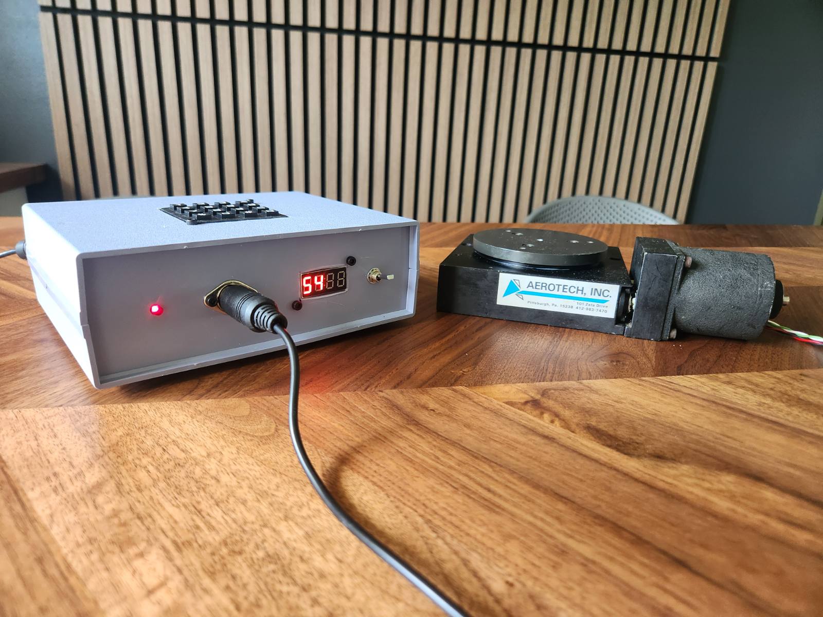
 Was this my cleanest encasement? Absolutely not. The 7-segment display is infuriatingly a little bit crooked and none of my cut lines are particularly straight, but I guess it adds to the charm. Most importantly, it works, and really well at that, and the case provides adequate protection for the sensitive electronics! The DIN connector makes it easy to untether the stepper from the controller for storage, and the big buttons and switches are easy to press even when focusing on keeping a pinion cutter happy :)
Overall, this was very much a success and I am quite pleased with the final product. It will get a ton of use in the shop :) Take a look:
Was this my cleanest encasement? Absolutely not. The 7-segment display is infuriatingly a little bit crooked and none of my cut lines are particularly straight, but I guess it adds to the charm. Most importantly, it works, and really well at that, and the case provides adequate protection for the sensitive electronics! The DIN connector makes it easy to untether the stepper from the controller for storage, and the big buttons and switches are easy to press even when focusing on keeping a pinion cutter happy :)
Overall, this was very much a success and I am quite pleased with the final product. It will get a ton of use in the shop :) Take a look: